Interfaces
The radar has physical interfaces that users physically connect to, as well as a standard digital interface that its data is channeled through.
Physical Interfaces
The following figure shows the top of the radar, where are all switches, interfaces, and inducators are located.
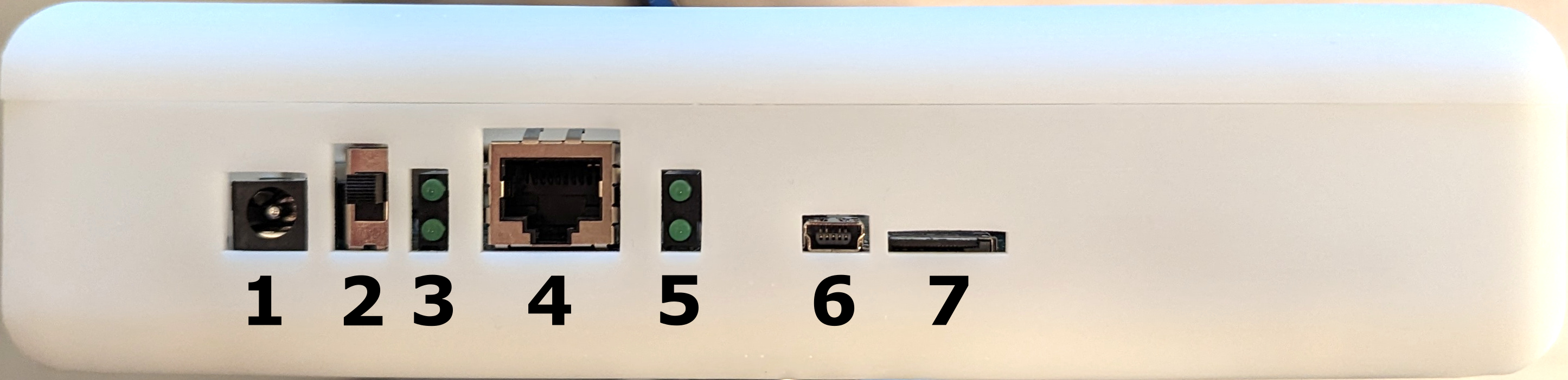
The top of the radar comprises the following set of ports:
- DC Power input. Requires 12V and a minimum of 2A of maximum current.
- Power switch (currently shown in the OFF configuration).
- Power ON LEDs. If the top LED is ON, the reader is being powered.
- Ethernet port.
- Ethernet activity LEDs. Ethernet activity is nominal when both of these LEDs are either blinking or ON.
- Serial USB port (only used for debugging).
- SD card slot. Used to change the radar setting, software, and firmware.
Data Interface
Once the radar is properly booted, it will send a constant stream of UDP messages describing the measured positions of nearby tags to the IP specified in its settings.csv file.
Data format
The UDP messages can have two different formats depending on the native coordinate system of the radar:
Spherical
{TagID:3B760CC2, Range:12.000, Elevation:3.000, Azimuth:-10.000, Mag:5.000, ReaderID:A4F7C965, Time:7.184}
TagID: 32-bit ID assigned to a tag, represented in hexadecimal format.Range: distance in meters from the reader to the tag.Elevation: elevation angle in degrees, relative to the reader.Azimuth: azimuth angle in degrees, relative to the reader.Mag: signal strength on a linear scale.ReaderID: 32-bit ID assigned to a reader, represented in hexadecimal format.Time: current time in seconds. Note that this value resets to 0 every minute.
Cartesian
In the cartesian case, the radar uses its position settings specified in settings.csv to calculate the cartesian position in the coordinate system of your choosing.
{TagID:3B760CC2, X:12.55, Y:3.91, Z:0.52, Mag:5.000, ReaderID:A4F7C965, Time:7.184}
TagID: 32-bit ID assigned to a tag, represented in hexadecimal format.X: X in the local coordinate system of your choice (in m).Y: Y in the local coordinate system of your choice (in m).Z: Z in the local coordinate system of your choice (in m).Mag: signal strength on a linear scale.ReaderID: 32-bit ID assigned to a reader, represented in hexadecimal format.Time: current time in seconds. Note that this value resets to 0 every minute.